| Radar systems, their components and relevant technologies |
|
Radar systems, their components and relevant technologies:
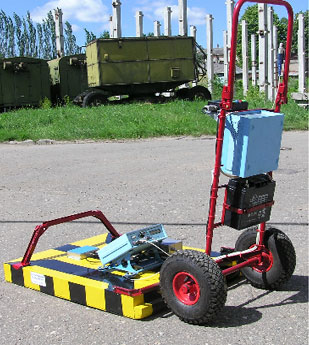
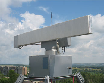
A) Scanning radar
Its operational purpose is to ensure radar subsurface probing in on-line and continuous monitoring of the surface medium structure on a real-time basis.
The communication with geographic coordinates is effected by means of global navigation systems. The georadar offers a fairly high mobility and can be used for geological operations in subsurface soil layers to search for mineral deposits, karstic caves, water-bearing strata. It can also be employed to monitor the state of foundations and other reinforced concrete structures, to detect underground service lines and to supervise the conditions of highways, air strips and railway tracks. Besides, it performs environmental quality monitoring, searches for objects of biological origin in optically non-transparent media and can be used for ice reconnaissance and in archeology.
The georadar parameters are listed in Table.
|
 |
| Georadar characteristics |
Value |
| Radiated power |
3 W |
| Operating frequency range |
100 to 450 MHz |
| Maximum probing depth as a function of soil moisture content |
20 to 30 m |
| Depth resolution |
15 to 30 cm |
| Radiation and signal reception attenuation in the upper half-sphere |
more than
40 dB |
| Antenna pattern above the Earth surface |
300 |
| Power consumption |
20 W |
| Weight |
19 kg |
|
|
|
|
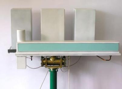
B) Millimeter wave semiconductor radar
The radar is intended for the control over activity on sites of district with a special mode. It carries out the viewing of airfield, runways and control of movement of air courts and vehicles on territories of air ports, the control of water areas of ports and navigation in passages.
|
 |
The note: characteristics presented below concern to system of the airfield viewing
The basic radar characteristics are |
|
|
1) Detection of the target having the effective area of dispersion more than 1 m2 with probability 0,9 at probability of a false alarm 10-6 up to
distances not less:
In conditions of clear weather - 5 km;
In a rain intensity 16 mm / hour - 3 km |
| 2) Angular resolution on an azimuth - is not less than 0,250 |
| 3) Range resolution - is not less than 15 m |
4) A zone of the review of space in horizontal area at height of installation of the aerial above a ground 5…10 m:
on range - 90 ….5000 m; on an azimuth - 3600 |
| 5) Time of the review (the period of updating of the information) - 4 s |
| 6) Suppression of preventing reflections from district and deposits - is not less than 30 dB |
7) Presence of system of automatic allocation and classification of the purposes on speed of movement (doppler selection)
Color marks of the purposes on the radar-tracking image on the screen of the monitor by high-speed criterion |
|
|
|
|
C) Noise Radar Technology
Noise Radar Technology (NRT) uses chaotic or noise (random) waveform (NW) as a radar signal and coherent processing for radar return reception.
Two methods for the radar return reception may be used:
(1) Correlation Processing, implying the use of a delay line,
(2) Spectral Interferometry, enabling range and velocity measurements without the need for a delay line.
FPGA-based signal processing enables performing of both types of noise radar return processing.
NRT offers a wide range of applications:
|
 Collision-warning/avoidance systems Collision-warning/avoidance systems |
| Intrusion detection sensor |
| Ground based synthetic aperture radars |
| Radar-reflectometer for measuring of electron plasma density profile and cutoff layer position in Tokomaks, the fusion plasma reactors |
| Forward-looking radars for automated aircraft landing systems |
| Airport runway surveillance and debris detection |
|
 |
| The following NRT based systems have been designed in LNDES: |
| W-band car collision-warning sensor |
| X-band noise surveillance radar |
| X-band ground-based noise waveform Synthetic Aperture Radar |
Ka-band noise waveform ground-based interferometric bistatic
Synthetic Aperture Radar for detection and measuring of
structural changes in natural and man-made objects, such as: |
| dams |
| towers |
| big buildings |
| hangars |
| |
|
|
|
|
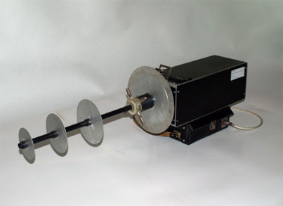
D) Radar for rescue operations
A portable radar unit (4.5 kg by weight) detects survivors beyond optically non-transparent obstacles (in the ruins of collapsed buildings and natural formations, the rubbles of destroyed walls and floors, among the debris and fragments of rooms, heaps of stones, etc).
This type of radar can be used for rescue operations under natural calamities and technogenic catastrophes, in worst-case accidents and
other emergencies. The radar characteristics are shown in Table below.
|
 |
| Radar characteristics |
Value |
| Range resolution |
0,5 m |
| Range |
10 m |
| Operating frequency |
1 GHz |
| Radiated power |
0,01 W |
| Power consumption |
20 W |
| Overall dimensions (with no antenna) |
150x150x350 mm |
|
|
|
|
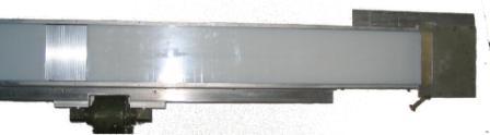
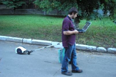
E) Videopulse subsurface georadar
This radar is used for subsurface high-resolution probing (no less than 15-20 cm) to depths of up to 2 m (wet clay) and up to 10 m (dry sand). It is highly efficient in probing operations for depths of up to 1 m.The radar is capable of surveying a path of 3 to 4 km in length per hour including computerized signal processing. It can be used to search for underground communications such as pipes (metallic and plastic), cables, etc. and to examine near-surface soil layers for diverse purposes. Provided that the georadar is intended to search for inhomogeneities in smooth-surface media, it is stocked additionally with a monopulse antenna system that provides a control display of objects and their more precise localization.
The main georadar characteristics are listed in Table.
|
 |
| Georadar characteristics |
Value |
| Pulse duration at the oscillator output |
1 ns |
| Range resolution |
in air: 15 cm;
in soil:
15 cm/
|
| Dynamic range (with no integration) |
90 dB |
| Continuous probing velocity including the data collection rate |
0.3 m/s |
| Power consumption |
8 W |
| Overall dimensions (with no notebook) |
0,3x0,6x0,1m3 |
| Weight (with no notebook) |
4 kg |
|
|
|
An antenna system has been specially developed for the georadar. It incorporates the method of complete frequency-independent isolation between
the transmitting and receiving modules.
The software package comprises:
|
| |
| loading programs and georadar control routine to be used in the probing processes |
probing data handling routine that includes the module of automatic search for local
objects |
To facilitate the procedure of interpreting radar subsurface probing a special purpose
software package has been developed for electrodynamic computerized simulation of
georadar image profiles of a subsurface soil structure of any geometrical and
electrophysical complexity with any temporal probing-signal parameters. |
|
|
|
|
|
|
|
F) Millimeter-wave small-size radar
It detects:
the presence of people on some locality (range is no less than 800 m), the means of transport (range is no less than 1500 m) and other objects. It likewise spots objects through noise caused by clutters from land surface, sea and hydrometeors (rain, snow, hail). The total weight of the radar and its constituent elements (a microwave unit with a rotary facility, a processing unit, stand-alone power supply) is equal to 18 kg. This arrangement can be easily moved or transported in any direction and is most efficient in standing guard over a state border, objects of exclusive importance and in improving the safety of railroad and motor transportation.
|
|
|
|
|
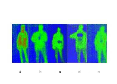
G) Radiometric system of thermal imaging of human beings
It detects foreign objects hidden under the clothes of human beings' bodies. The effective range of this system is 3.5 m. It can easily be used by security officers at airports, in railroad and underground (subway) stations and other heavily crowded places.
A receiving aperture incorporates an electro-dynamic structure that uses the principle of converting volume electromagnetic waves to surface ones. It comprises a metallic diffraction grating as a disk and a dielectric waveguide.
These elements are technically realized in a scanning antenna whose beam position is electromechanically controlled. The entire system is operated between 86 and 100 GHz in an angular sector 340x140, its number of channels being equal 16 (32). The observation field is 1,0x2,0 m2 for a 3,5 m distance to an object. This development has been obtained together with "NPP"Saturn".
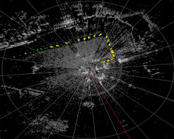
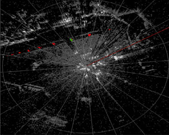
Some radio-thermal human images in 3-mm band of wavelengths are presented below:
|
|
 |
 |
| natural distribution of brightness (а) |
| belt of hunter under clothes (b) |
| other foreign objects under clothes (c, d, e) |
|
|
|
H) Aviation forest air protection radiometer
This radiometer is capable of providing reliable information on a site of forest fire, specifically, the position of a burning edge around it. It detects the extent of an active burning zone in crown, ground (hidden by a forest canopy) and subsurface fires (in peat-bog areas). Using the frame scanning of space allows getting advanced (in flight) data on fire site coordinates. The raster-related viewing technique is found to be more promising in terms of tackling the operational issues pertinent to analyzing incoming data and maneuvering an airborne vehicle in fire emergencies. This system uses the scanning method in the along-the-flight track sector of angles, a multibeam antenna pattern with beams lying in a plane orthogonal to a flight direction.
The basis radiometer characteristics are listed in Table below.
|
|
 |
| Radiometer characteristics (altitude 1000 m) |
Value |
| Operating wavelength |
3 mm |
| Number of operating beams |
32 |
| Scanning sector |
±600 |
| Antenna aperture diameter |
400 mm |
| Space resolution in centre of a frame |
8x8m2 |
| Swath width in centre of a frame |
~300 m |
| Channel sensitivity |
1÷1,5 К |
| Probability of detecting of a fire site 10 m2 |
0,95
(in a false alarm 10-4) |
|
|
|
|
| The radiometric images are constructed in the course of data processing aboard an aircraft and the formed pictures are being displayed on a real-time basis. An algorithm for constructing images enables one to assess the efficiency of employing fire-extinguishing means with a symmetric scanning sector (in forward and backward flight).
|
|
|
|
|
I) Multifrequency conical-scanning radiometric complex (RMC)
The complex is intended to produce radiothermal images of the Earth's surface from airborne vehicles (man-made satellites, helicopters and aircraft)
in six frequency subranges of the electromagnetic spectrum. Space scanning is performed by rotating an antenna around its axis as it is oriented-to-nadir, along a conical envelope, with an angle of sight ( of 45,50). Rotation is circular, one-way, continuous with a period of 1,2 - 2 s.At altitudes between
600 and 900 km it provides for surface observation in a swath width of 900 to 1400 km at a surface-element observation angle of 51,30 - 54,50.
The basis characteristics of RMC are given in Table below.
|
|
| |
| RMC characteristics |
Value |
| Working sector of azimuthal angles |
±420of flight direction |
| Side-lobe level of antenna patterns |
27÷30 dB |
| Polarization isolation between channels |
no less than 25 дB |
| RMC continuous operation time during a single session |
up to 12 hours |
| RMC output data stream rate with data blocking |
up to 60 KB/s |
|
|
|
|
J) Receive-transmit scanning antennas based upon the conversion of surface electromagnetic wave to volume ones
The unique electrodynamic properties of the antennas under development, which use the effect of converting surface waves to volume ones on periodic obstacles, allow employing these antennas in constructing microwave radiometric scattering systems with a goal of studying the environmental situations and ensuring hidden observation of objects for the benefit of customs and guard services.
The antenna systems (AS) under development are extensively used in active local Earth's surface viewing systems to detect and identify all types of objects.
|
|
|
|
| Currently the AS find their application in radiometric complexes and airfield viewing radar facilities.
|
|
|
|
|
K) Hypersound delay lines (HDL) of microwave signals
The HDLs serve as storage devices of microwave signals and were the first to be proposed and developed in the world by the Usikov Institute of Radiophysics and Electronics of the NAS of Ukraine. Their operation is based on converting the microwave electromagnetic wave to a hypersound one, propagating this wave through an acoustic line and its inverse conversion to an electromagnetic one. The HDLs allow a long-duration microwave signal delay when this signal is kept coherent with respect to an input signal. This essential feature of the HDLs makes it possible to be applied in all-purpose radar systems. Nowadays the HDLs are used as a signal calibrator in side-looking radars installed on a man-made SICH-1 earth-orbiting satellite.
|